Smartphone Controlled Programmable Robotic Arm
[Project Blog – B.Tech 3rd Sem]
Welcome to my detailed project blog on building a smartphone-controlled programmable robotic arm! This project combines the power of Arduino, Bluetooth communication, and mechanical design to create a versatile robotic arm that can be controlled wirelessly using a smartphone. Whether you're a student, hobbyist, or professional, this guide will walk you through every step of the process.
Robotic arms are revolutionizing industries by automating repetitive tasks, increasing precision, and enabling new possibilities in manufacturing, healthcare, and research. This blog explores the journey of building a smartphone-controlled programmable robotic arm, designed for flexibility, ease of use, and educational value.
Our project aims to bridge the gap between software and hardware by integrating a 4 DOF robotic arm with a smartphone interface. This allows users to control the arm's movements wirelessly, making automation accessible even to those without advanced programming skills.
Key Features & Advantages
The robotic arm is powered by an Arduino Uno, controlling four gear motors via a motor driver shield. A Bluetooth module enables wireless communication with a custom smartphone app, allowing real-time control and programming of the arm's actions. The modular design makes it easy to upgrade or modify for different use cases.
How It Works
The user connects their smartphone to the robotic arm via Bluetooth. The app provides sliders and buttons to control each joint of the arm, enabling precise positioning and movement. The Arduino receives commands and translates them into motor actions, executing complex tasks with ease. The system is designed to be intuitive, so even beginners can start automating tasks quickly.
Circuit Diagram
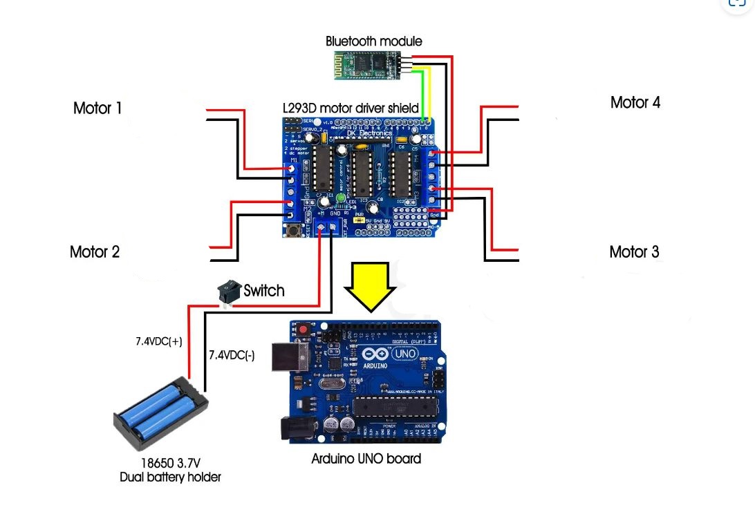
The circuit diagram above shows the connections between the Arduino Uno, motor driver shield, Bluetooth module, and the four gear motors. Proper wiring and power management are crucial for smooth operation and to prevent damage to components.
Components Used
Mechanical Design & Assembly
The arm is designed with modular joints and a sturdy base, allowing for stable movement and easy upgrades. 3D-printed or laser-cut parts can be used for the frame and gripper, while the gear motors provide precise control over each axis. Assembly instructions and CAD files are available for customization.
Software & Programming
Sample Arduino Code
The Arduino code is designed to control the motors based on commands received from the smartphone app. Each command corresponds to a specific movement of the arm, allowing for precise control over its actions. The code is modular and can be extended for more complex automation tasks or additional sensors.
Sample Arduino Code
Below is a sample Arduino sketch for controlling the robotic arm's four motors using serial commands received via Bluetooth. Each command (F, B, L, R, G, I, H, J) corresponds to a specific movement or joint action. This code can be extended or modified for more complex automation tasks.
#include <AFMotor.h>
AF_DCMotor motor1(1);
AF_DCMotor motor2(2);
AF_DCMotor motor3(3);
AF_DCMotor motor4(4);
int Speed = 230;
char value;

void setup() {
  Serial.begin(9600);
  motor1.setSpeed(Speed);
  motor2.setSpeed(Speed);
  motor3.setSpeed(Speed);
  motor4.setSpeed(Speed);
}

void loop() {
  if (Serial.available() > 0) {
    value = Serial.read();
  }
  if (value == 'F') {
    motor1.run(FORWARD);
    motor2.run(RELEASE);
    motor3.run(RELEASE);
    motor4.run(RELEASE);
  } else if (value == 'B') {
    motor1.run(BACKWARD);
    motor2.run(RELEASE);
    motor3.run(RELEASE);
    motor4.run(RELEASE);
  } else if (value == 'L') {
    motor1.run(RELEASE);
    motor2.run(BACKWARD);
    motor3.run(RELEASE);
    motor4.run(RELEASE);
  } else if (value == 'R') {
    motor1.run(RELEASE);
    motor2.run(FORWARD);
    motor3.run(RELEASE);
    motor4.run(RELEASE);
  } else if (value == 'G') {
    motor1.run(RELEASE);
    motor3.run(FORWARD);
    motor2.run(RELEASE);
    motor4.run(RELEASE);
  } else if (value == 'I') {
    motor1.run(RELEASE);
    motor2.run(RELEASE);
    motor3.run(BACKWARD);
    motor4.run(RELEASE);
  } else if (value == 'H') {
    motor1.run(RELEASE);
    motor2.run(RELEASE);
    motor3.run(RELEASE);
    motor4.run(FORWARD);
  } else if (value == 'J') {
    motor1.run(RELEASE);
    motor2.run(RELEASE);
    motor3.run(RELEASE);
    motor4.run(BACKWARD);
  } else {
    motor1.run(RELEASE);
    motor2.run(RELEASE);
    motor3.run(RELEASE);
    motor4.run(RELEASE);
  }
}
Mobile App & User Interface
The custom smartphone app is designed for ease of use, featuring sliders and buttons for each joint. The app communicates with the Arduino via Bluetooth, sending single-character commands for each movement. The UI is intuitive, making it accessible for users of all skill levels.
Testing & Troubleshooting
During development, thorough testing was performed to ensure reliable communication and precise movement. Common troubleshooting steps include checking Bluetooth pairing, verifying wiring, and calibrating motor speeds. Debugging tips and FAQs are provided in the project documentation.
Applications
Further Enhancements & Future Scope
Conclusion
This project demonstrates how combining software and electronics can lead to powerful, user-friendly automation solutions. Whether for industry, education, or hobbyist use, a smartphone-controlled robotic arm is a great way to explore robotics, programming, and mechatronics. The open-source nature of this project encourages further innovation and collaboration.
Have questions, suggestions, or want to collaborate? Leave a comment below or reach out via the contact page! For more projects and tutorials, explore the rest of my portfolio.